Technology
In order to obtain a spectral dispersion, different spectrometer concepts are used for spectral imaging.
- Multispectral imaging:
- Multi-sensor: beam splitter and use of filters for several sensors; usually <10 spectral channels
- Multi-channel: spectral dispersion using special prisms with a spectral gradient filter; approx. 10-20 spectral channels
- Filter-on-chip: Fabry-Perot filters imprinted directly on the sensor chip; often 16 or 25 spectral channels (4x4 or 5x5 arrangement of channels)
- Hyperspectral imaging:
- Filter-on-chip: linear, spectral gradient filters applied directly to the sensor chip; often 100-200 spectral channels
- Holographic gratings in transmission or reflection (e.g. Offner setup); over 1000 spectral channels
The spectrometers used to date for hyperspectral imaging are all dispersive. They are less sensitive than conventional laboratory spectrometers, especially those based on the Fourier transform (FT) technique. However, the advantage of the systems lies in the use of spectral information in the area. Deviations in the area can be detected even with a poorer signal-to-noise ratio.
Just like the spectrometers of the HSI systems, the detectors are also tuned to a defined spectral range. Conventional silicon detectors (Si) are used for the spectral range from approx. 250 nm to approx. 1000 nm, while special semiconductor materials such as indium gallium arsenide (InGaAs) or mercury cadmium telluride (MCT) are used for the near infrared range above 1000 nm. Frequently used and commercially available spectral ranges for hyperspectral imaging are listed below.
- approx. 250 nm - 500 nm ultraviolet/visible (UV/VIS) with UV-enhanced silicon detector
- approx. 400 nm - 1000 nm visible/near-infrared (VIS/NIR; also known as VNIR) with silicon detector
- approx. 700 nm - 1600 nm near-infrared (NIR or SWIR for 'short wave infrared) with InGaAs detector
- approx. 1000 nm - 2500 nm near-infrared (NIR or SWIR for 'short wave infrared') with MCT detector
Depending on the detector, HSI systems now achieve up to 400 Hz at full resolution and >1000 Hz with binning or by selecting individual spectral channels (region of interest, ROI).
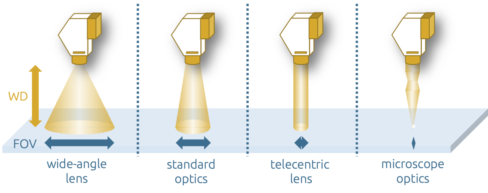
The optics/lenses of most HSI systems are variable, e.g. via the industry standard C-mount. This results in a wide range of configuration options, as illustrated in Fig. 3. The minimum working width of the HSI system is determined by the focal plane of the lens; in addition, the working distance (WD) can usually be freely selected. The resulting field of view (FOV) can therefore be set from a few millimetres (microscope) to several meters or kilometers.

Hyperspectral imaging: field of view in different optics configurations
The theoretical spatial resolution of the scan line (x-coordinate) can be determined directly from the field of view and the available number of pixels of the detector; in reality, the resolution is also significantly influenced by the quality of the holographic grid. The spatial resolution of the y-coordinate, on the other hand, depends on the measurement parameters selected later, such as the measurement frequency of the detector and the speed of the samples. Therefore, hyperspectral data can have square pixels, but depending on the recording mode, the pixels can also be compressed or stretched. The spectral resolution (z-coordinate) depends on the combination of holographic grating, detector and input slit and is documented on the manufacturer's data sheets or calibration. When planning inspection tasks using HSI, it should also be taken into account that not all wavelengths can be imaged sharply at the same time due to the optics. The focal plane is not only shifted along the z-axis, but also by the wavelengths.
